In one of my previous posts about the restoration of the old German radio that my girlfriend gave me, I took out the old tube amplifiers and saved them. Now that time has come for the project within the project.
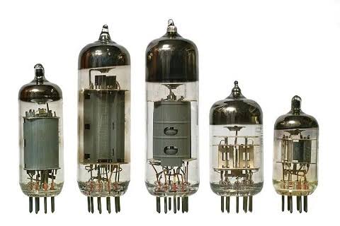
Leftover Vacuum Tubes.
Since I do not want to work on the old radio and reuse the tubes for the actual purpose, I have decided to repurpose them for an arts display. They look cool and why shouldn’t one show off all the cool things that engineers used to build products with. The style of Nixie tubes have always intrigued me, but I don’t want to make the all to common Nixie tube clock. I actually don’t want to make a clock at all.
All I want to do is to be able to look at them and admire how much harder it was to work on amplifiers back then. With all the bias voltages, non-linear behaviour and crazy high supply voltages.
So, I decided to make a Nixie clock style display to show off the tubes. To make them pop even more, I will be putting an addressable LED under each of them.

Example of a very pretty Nixie tube display
This will shine through the tube and hopefully give it a nice effect. I will be using the WS2812B LEDs so I should also be able to make some cool effects. Plus it will be easier to choose the color that fits the display the best. Anyone that knows me will know that I hate RGB LED effects that is everywhere at the moment. But I am generally a fan of the idea of being able to tune a constant color for your designs. Or even change it when you grow tires of it.
It’s too wobbly
First things first, I have to have some way to keep the tubes stable while standing up. I have 5 tubes with a ECH81 footprint and I thought the easiest way to do this, was to get them on a PCB. But proper mounting of the tubes will eleminate the possibility of having a WS2812B directly beneath them. The height of the LEDs is simply too big. To solve this issue, I could have just went with a smaller LED. But I already have these in stock and I want to use them. Kinda putting a restriction on myself here, but there is another way to solve the problem.
Make a drill hole in the PCB exactly the same size as the round opening on the WS2812B. Then shine the light from the bottom up. The biggest issue with this approach: The LEDs have to be reverse mounted. Ugh, that is a pain for this footprint. But I am willing to suffer to mount these 5 LEDs.
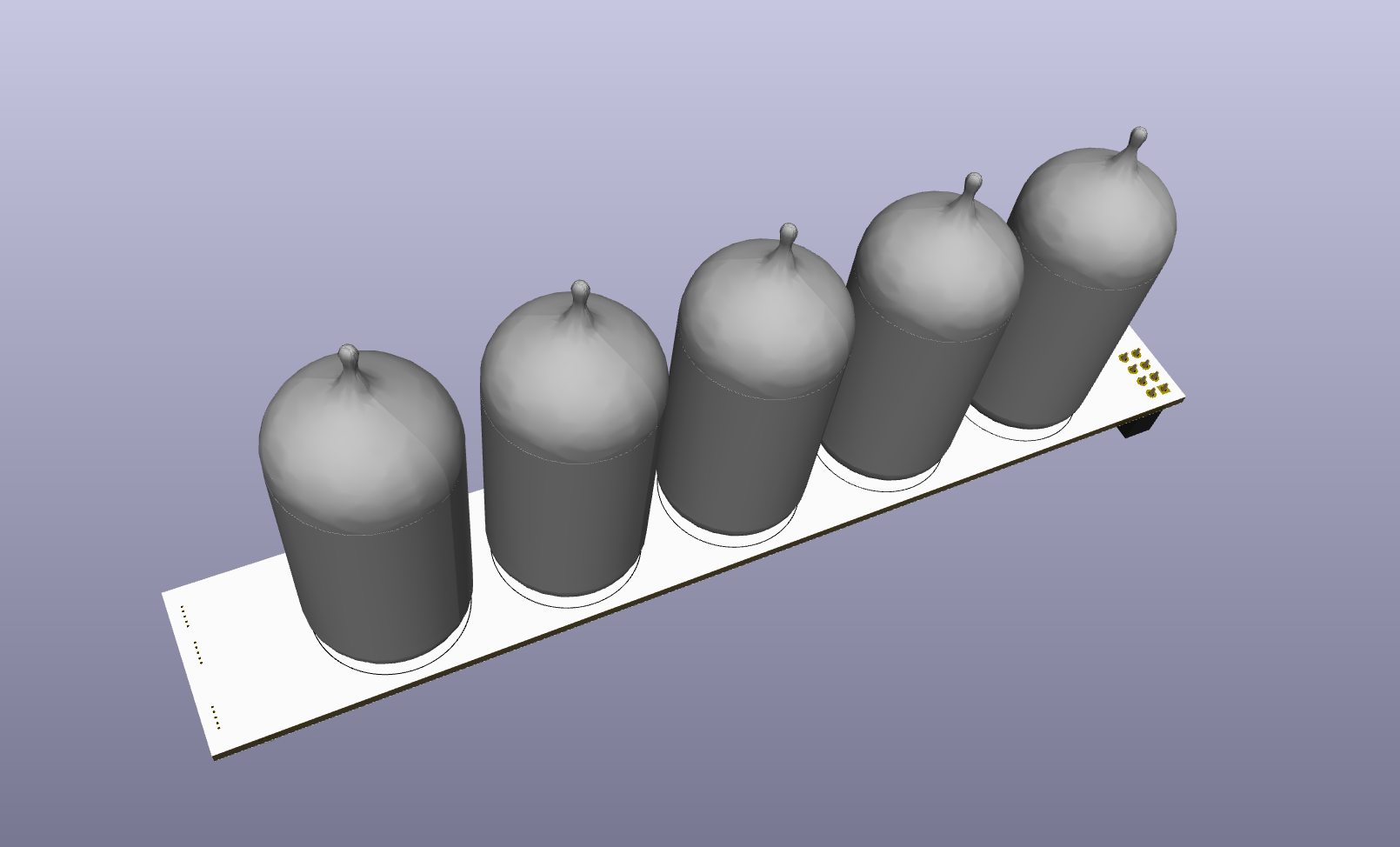
3D model of tube mounting PCB
My first design was to simply have the tubes on one PCB. Then copy the exact PCB cutout to a new layout and create the controller on there. The controller could then easily be connected to the tube board by pin header connectors.
Controlling the chaos
For controlling the LEDs I first wanted to use an Arduino to keep the power supply simple. Since the Arduino Nano dev board can be supplied by 5V, same as the LEDs. No level shifting would be needed for the data signal either.
But I realized the Arduino is too dumb and needs to many external sensors to do what I actually wanted. For example, if I only wanted the display to be turned on during the evening time, where you can actually see the lights. Then I would have to either have and RTC or do some sort of tricks with an ambient light sensor. Not great. I was also toying with the idea of using a proximity sensor to turn on the displey if someone was close. I could still do this at a later stage. But for now, this became too complicated for such a simple thing.
So I opted to switch to an ESP8266, which is even smaller, great!
Now we have WiFi support and I will be able to just connect to a NPT-server and then have the current time of day at my location. Cool, then I can actually turn the display on automatically and turn it off sometime after I have definitely gone to bed.
Using the ESP8266 is easy since we only need one data line to the LEDs to program them. However, the input voltage to the ESP is 3.3V which is the enternal struggle when controlling LEDs. We now need two power supplies.
Luckily, it is quite easy to obtain a 5V supply from a simple wall adapter. The 3.3V can then be created using a simple LDO as the voltages are quite close and the ESP8266 requires less than 100 mA in operation.
The first iteration is never the last
As I said earlier, I wanted to have a PCB with the tubes mounted on that would connect to a similar PCB with all the control stuff on it. This was the initial idea when I was planning on using the Arduino. I even had the first drafts of these PCBs manufactured at JLC.
But as we often do, I realized the design was stupid (see above) and decided to change it.
The Arduino and the sensors were too large to fit on the bottom side of the tube PCB. But now that we have thrown that out and are using the ESP8266 instead, there would be enough space to fit everything on one PCB. If there is anything I have learned professionally and in my own projects by now is that, one PCB is better than two in 99% of the cases.
So without even mounting the components on the old PCBs, I redesigned them to fit the tubes on the top side (with their THT footprint). And all of the control infrastructure on the bottom side alongside the WS2812B LEDs that will still shine through their holes.
The schematic for the second version can be seen below
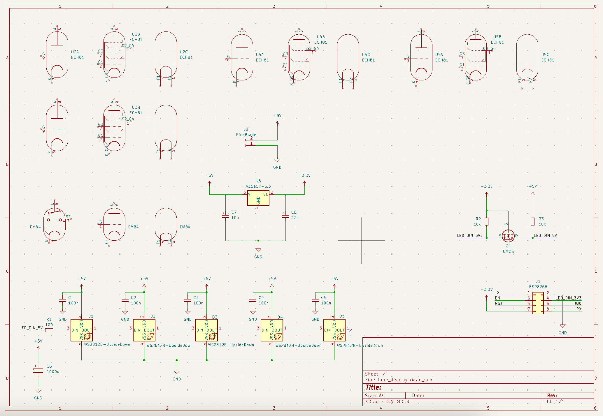
Schematic for the display
I have just used 5x a generic footprint for the tubes. The 5V supply will come from a wall adapater that can attach with a magnetic connector (trying out my 3D modelling skills later) to the case. The 3.3V is generated using a standard AZ1117 or similar type LDO. The ESP8266 will connect through the standard interface of a 4x2 pin header. The WS2812B are also quite standard. Other than the fact that I have created a new schematic symbol and footprint for them in order to more easily mount them upside-down (already learned this lesson).
The logic level shifting from 3.3V to 5V is done usin a simple MOSFET. Since we don’t need bidirectional communication, this is super easy.
And that is pretty much it.
The final PCB design looks like this.

KiCAD PCB view
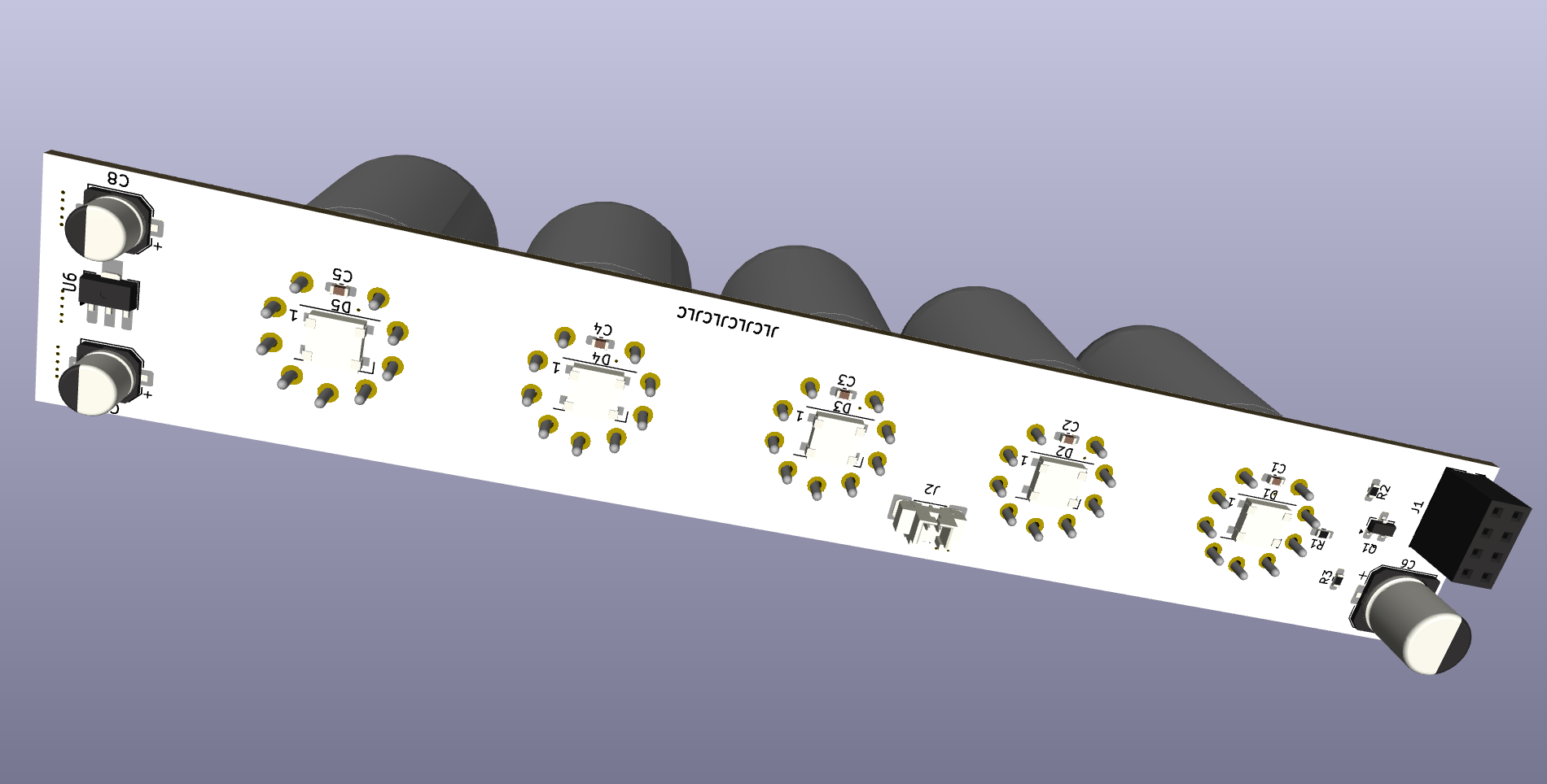
KiCAD PCB view in 3D
Let’s ship it to JLC and see what comes out of it.
Making the case
While waiting for the PCBs to come, it is always a very productive past time to work on the case.
I will be using OnShape to create the case. I love this tool because it is super easy to learn (if you have a little CAD experience) and it is browser based. Meaning I don’t have to install anything. Some people say that they don’t like the browser based tools since they cannot work offline then. But I never like to do CAD away from my big monitor and mouse. So for me it is perfect. They even have a free plan for hobbyists.
The case will be super simple. I will create a small top piece that will house the PCB and have the hole cut out for the tubes.
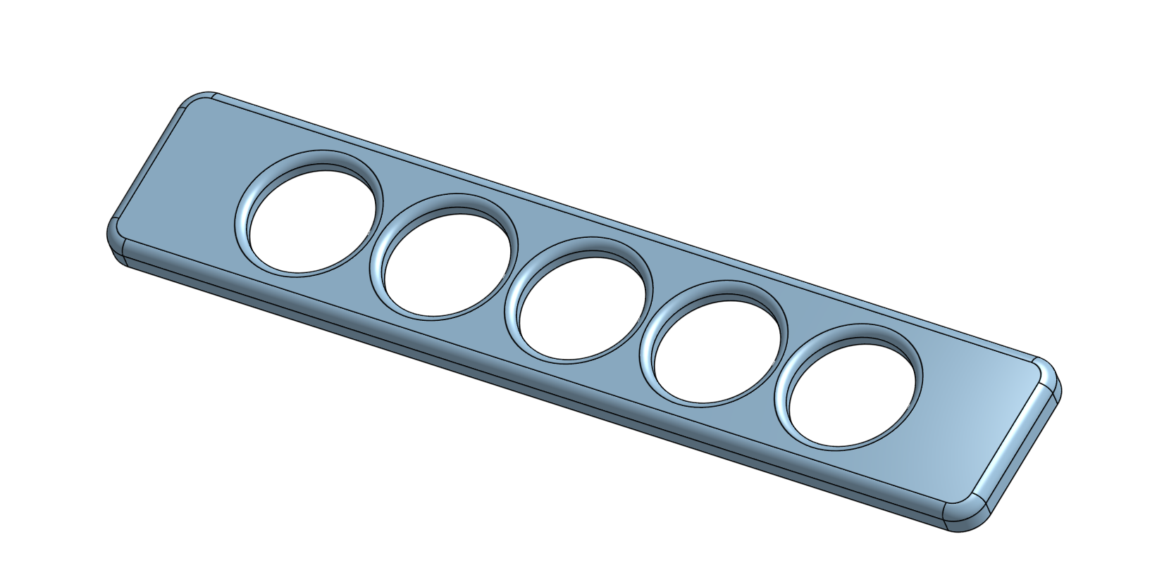
Top side of top piece
To attach the PCB, I made a cut out with the dimensions of the PCB plus some tolerance. I also added two screw holes so I can attach two M2 screws to hold it in place just in case.
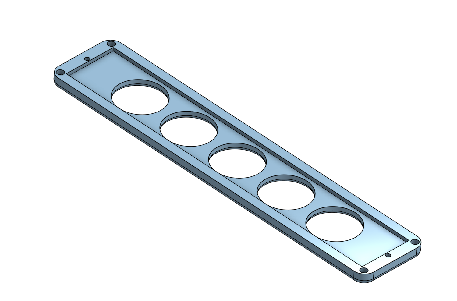
Bottom side of top piece
The bottom piece will then only exist to hold the wiring and make it a little taller. The two pieces will snap together using a magnet in each corner.
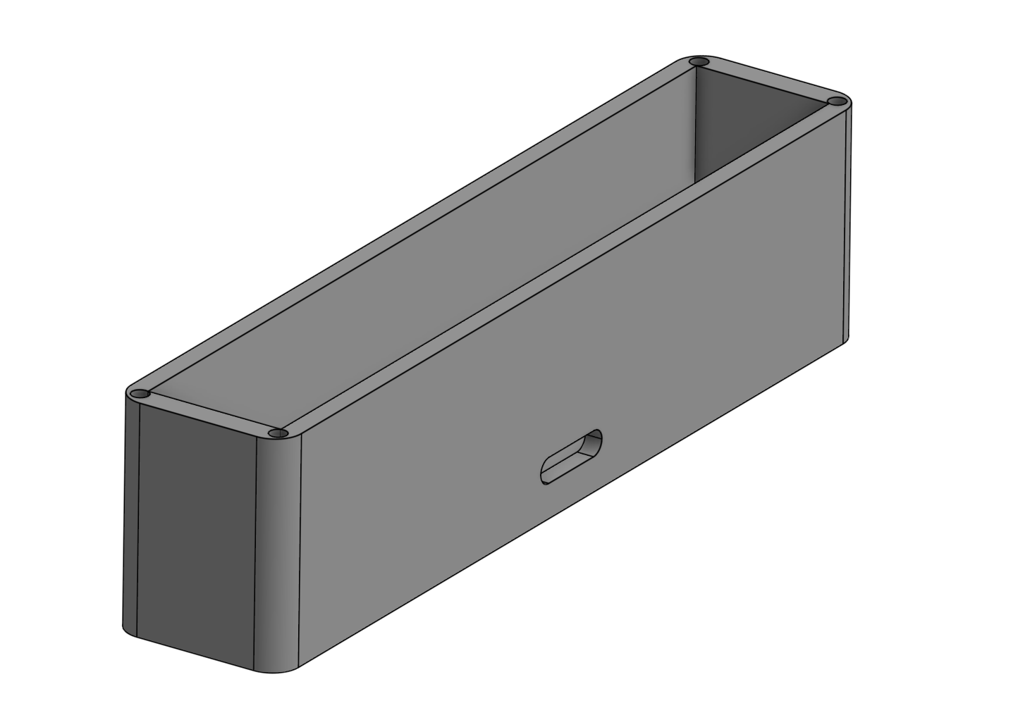
Bottom piece
The bottom piece will also have a hole cut out in the bottom so I can mount the magnetic power connector to the 5V supply.
After creating the design for the case, I 3D printed it on my Elegoo Centauri Carbon, which worked wonderfully!
Follow along in the part 2 blog post to see how it all fits together.