For our 5th semester project, my group and I chose to work on a project that I proposed. I had seen some attemps at making drones that could be used for avalanche rescue operations, but none of them seemed to work very well. So we decided that we would investigate and see if we could make such a drone ourselves. This was definitely one of the most extensive projects during my university studies.
The 5th semester of the EE bachelors at AAU is focused around Control Systems, Signal Processing and Wireless Systems. So we knew we had to incorporate some of that into the project. Given that we would be working with drones, we thought the Control Systems part would be pretty easy to cover. Signal Processing would be covered by the fact that we had to analyze an analog signal coming from the antenna (or actually rather coil) on the drone. Given that signals were transmitted wirelessly, the Wireless Systems were also easily covered.
We started off by borrowing a DJI Matrice 100 from the Wireless Systems department. The drone had a UART interface and an SDK from DJI. We could then connect a Rapsberry Pi through UART and mount it on top of the drone. The plan was then to have the math run on the Pi and let it send commands to the drone accordingly. We had inteded to power the Raspberry Pi directly from the Matrice’s battery pack, but the 22 V nominal battery was to much to handle for a Linear Regulator, so we ended up mounting a two 18650’s in series to power the Pi.
Avalanche transceivers generally work on 457 kHz and are made up of 2 – 3 coils wrapped around a ferromagnetic material. The coils are oriented at 90 degree angles of each other, such that the magnetic field they produce does not cancel out. Orienting them this way makes in possible to find the transmitter from a multiple of angles. Due to the fact that it is the magnetic fields and not the EM field that is being utilized for the search.
We chose to use a rather large signal chain. So from the coils, the signal was routed to an LNA that we designed with discrete components, then an analog bandpass filter, Anti-aliasing filter and lastly being DC-offset before the ADC would sample the signal. We chose to use an ADS7883 for the sampling since we did not want to add comlexity by adding a down mixer. The ADS7883 had an adaquete sampling rate with 12 bits of resolution. Meaning we could detect the signal from further away.
To design the coils, we used the equivalent circuit shown below.
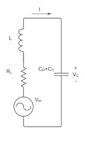
The coils were made by wrapping some coated wire around a ferromagnetic rod which increased the inductance of the coil. We could the tune it to the resonance frequency we wanted by varying the capacitor connected across the coil terminals. Unfortunately, the pictures I had of the coils were lost. We ended up with a Q value of the coil of 45 and we were able to tune the antenna to the required frequency.
From theory of how strong the field emitted by Avalanche transceiver should be, we could calculate a signal strength over distance and plot it. We could then measure the signal strength of our designed antenna and see if they matched up. The result can be seen in the figure below.

x-axis shows the distance between the transmitter and receiver and the y-axis shows the expected voltage across the coil. The blue solid line shows the signal strength to distance with the lowest allowed signal strength of the transmitter. The red solid line shows the highest allowed signal strength. The dots are our measurements. The reason for the difference in colors for our measurements is because we had to use amplification after 3-4 meters. Otherwise the signal would be too weak to visually identify on an oscilloscope.
The LNA that followed the coils were designed with a differential amplifier BJT circuit, biased by a Wilson Current Mirror. Further voltage amplification was achieved with an output compound coupling. Circuit is shown below.
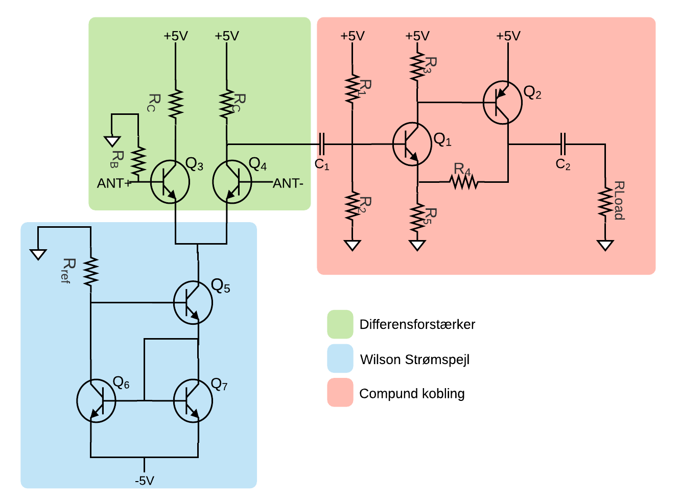
It gave a descent frequency response. But I am not sure that we actually made it that low noise… We should probably have been using MOSFETS instead, but hey… We had fun and learned.
The bandpass filter was implemented as a Sallen-Key topology, which implements an active second order filter. Calculations and implementation was made according to the very nice handbook from Analog Devices.
I won’t get more into the anti-aliasing filter as this is pretty standard to use when sampling a signal that you want to further analyze and work on discretely. We had to implement a DC-offset as well because the ADC would not go to negative voltages.
After sampling we had a digital filter which I won’t get into either because it was unecessary to have and very badly designed and implemented. But we wanted to try it out since it was a part of our curriculum.
So at this point we pretty much just had to do some math work on the sampled signals and then steer the drone in the direction the math told us. Then came the second COVID lockdown and we were unable to sit in the same room and work on the drone. So our solution was to simulate everything. Luckily, DJI also provided a simulator with the they provided. Only problem is that the drone has to be connected to the computer in order for the simulation to work. Which meant that only one person could test the drone software at a time, which does become pretty tedious for the person testing.
To do a control system for the drone, we tried measuring the drone’s step response. This we thought would be a good idea since we might need the drone to turn fast when searching. So we went out in a low wind day with a preprogrammed Rasperry Pi. The Pi was to change the yaw of the drone 5 degrees as fast as possible. Then we could record the yaw angle during the procedure. Using that data, we were able to make a 2nd order approximation of the system. We tried using the MATLAB System Identifier tool to confirm the approximation, but the tool showed that a fifth order system was needed to most accurately model the response. The measured response and approximations is shown below.
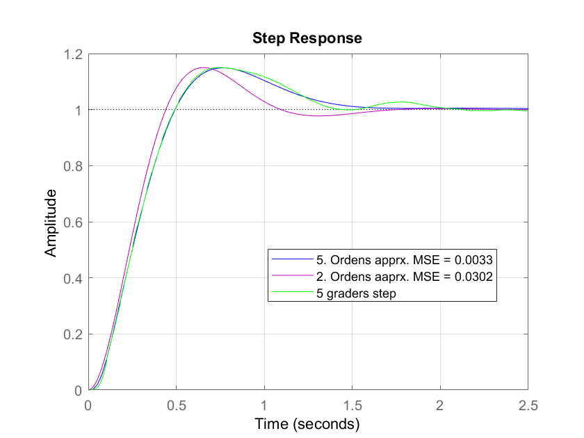
Measured step response, 2nd order approximation and 5th order approximation. However we decided to work with the 2nd order approximation since the MSE was still quite low. Though we actually ended up scrapping it, since our conclusion with multiple simulations, was that DJI has (surprise surprise) made a pretty good control system, and our system did not gain anything from us messing with it. A flow diagram of the entire system can be seen below.
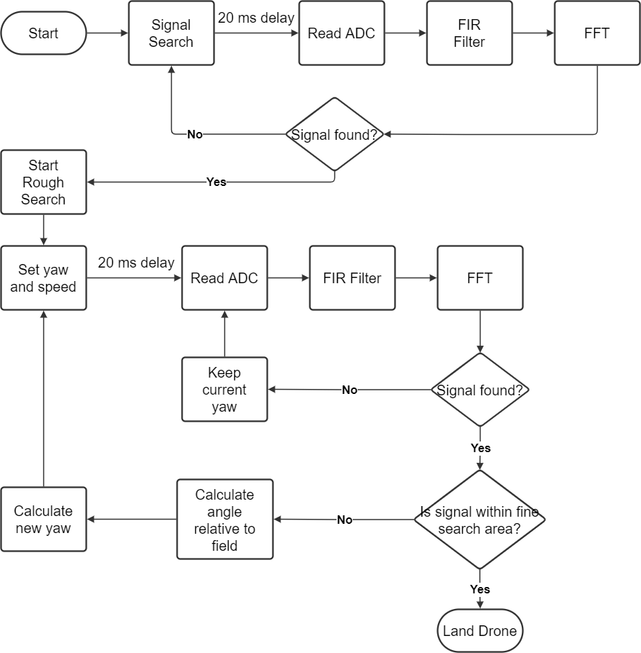
So search areas were split into rough search and fine search. Rough search is where the drone is actually helpful. The idea is that the drone will find the signal from 50-100 m away and then land within 1-3 meters of the buried person.
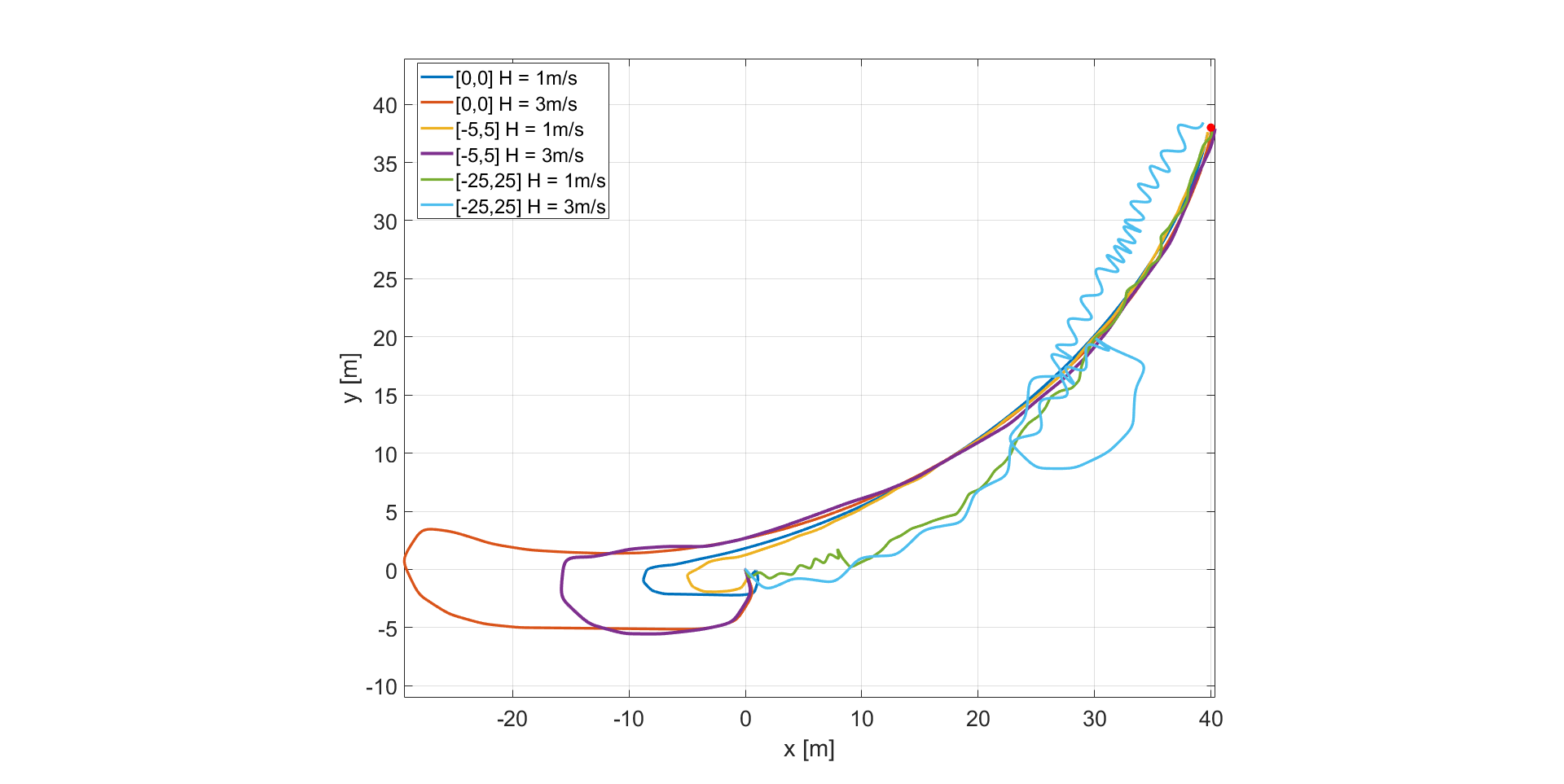
Simulations showed that the algorithm and system on the Pi would work. However we never got to test it out in the world. Below is a plot of the simulation results. The drone starts at position [0,0] and the transmitter is located at [40,40]. Various amounts of noise was introduced to the system and signal to stress test.